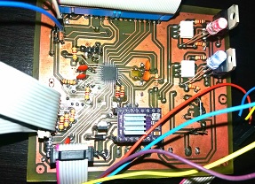
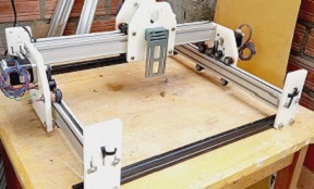
Development of custom electronic boards with CNC Router.
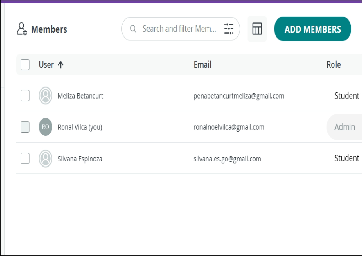
In this step it is crucial to activate sharing within your account, as interaction will be required. An invitation was made to another person, in my case a colleague from Fabacademy
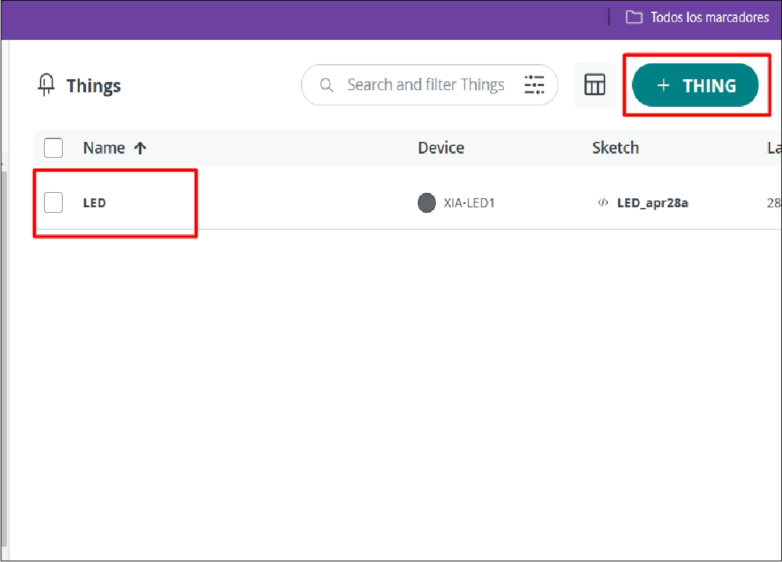
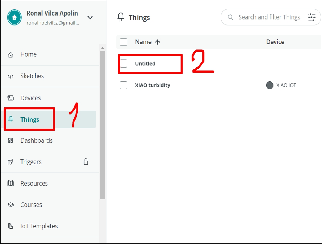
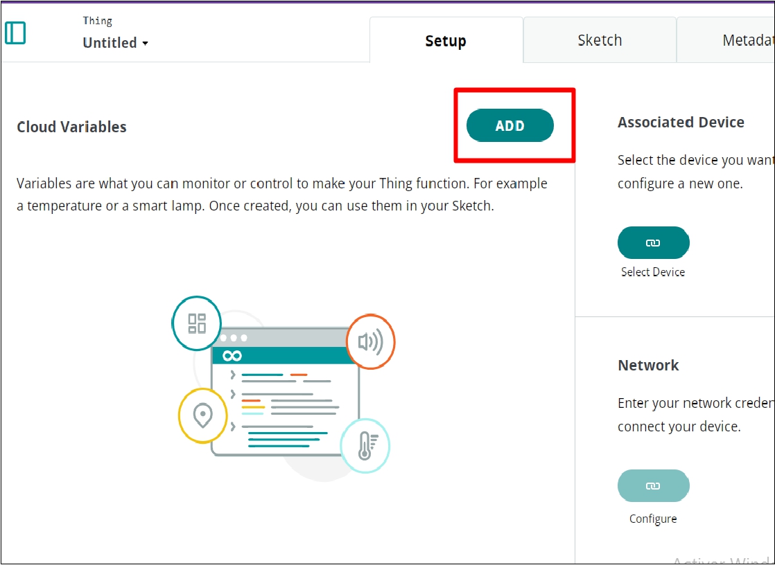
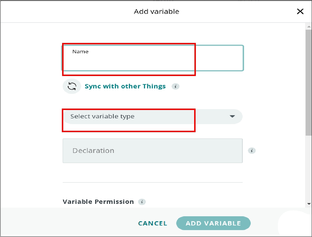
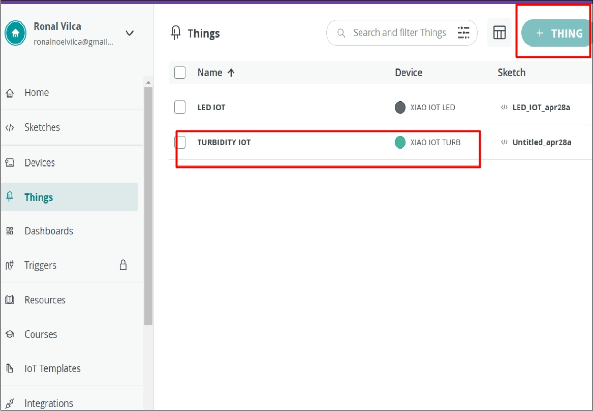
Once sharing is enabled, we proceed to create the dashboard, device and thing on the Arduino IoT Cloud platform and then configure them according to our needs.
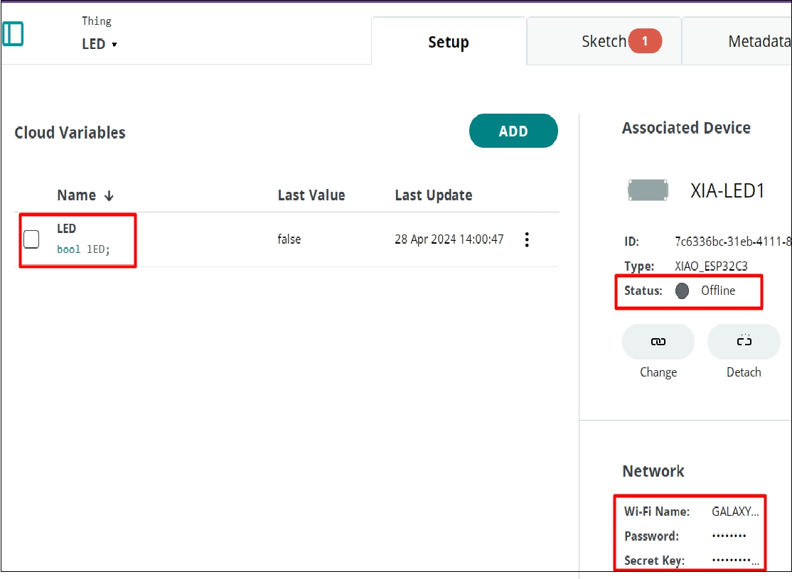
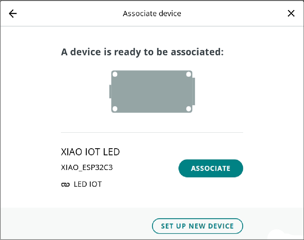
Once the interaction is configured and created, which can include anything from an LED to actuators, the next step is to configure the WiFi credentials, password and security key. Subsequently, we proceed to load the program into the XIAO ESP32 with the desired interaction
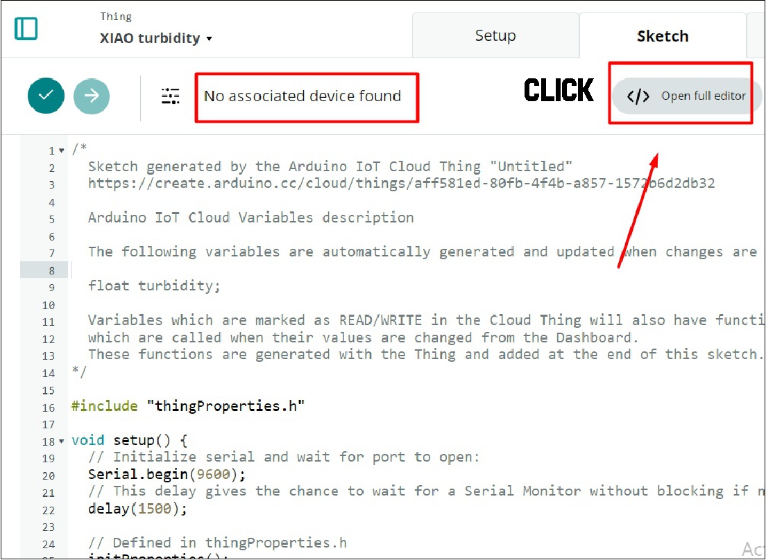
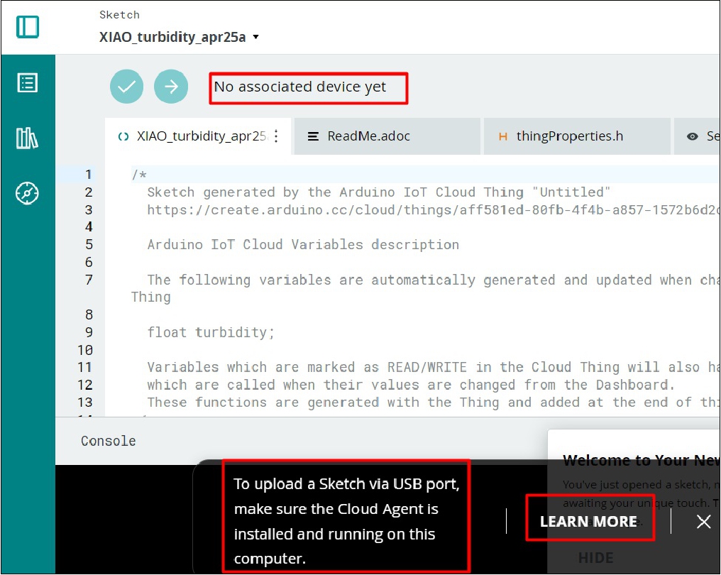
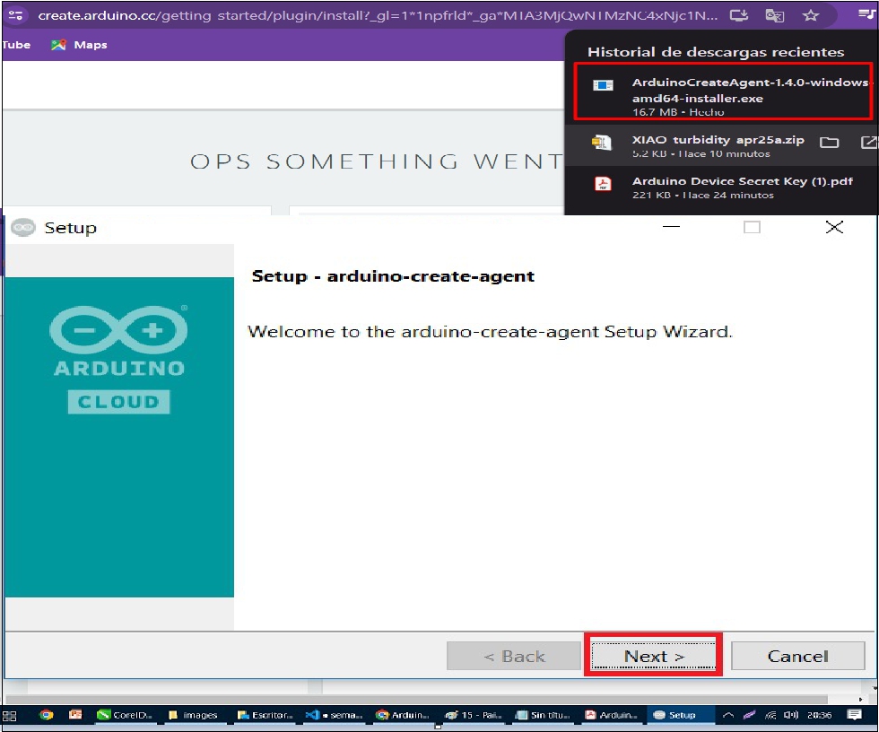
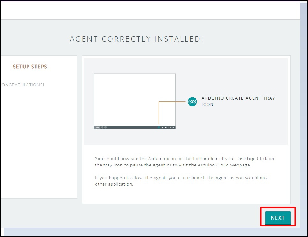
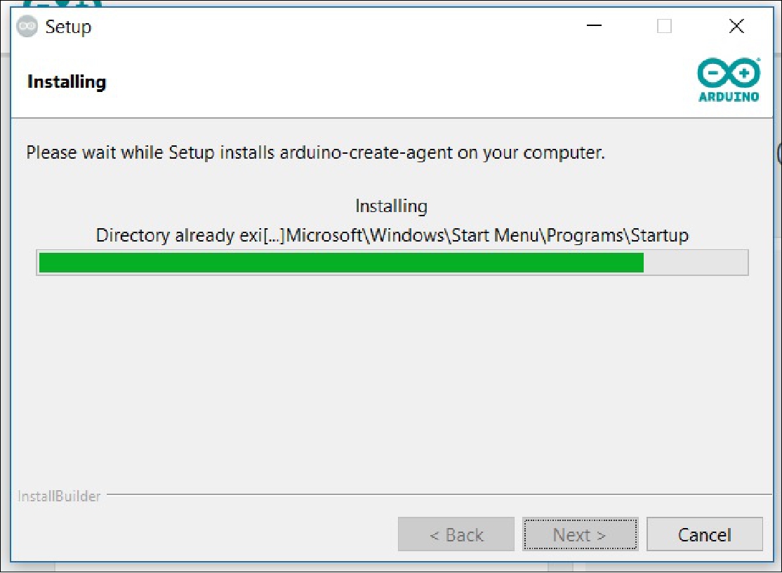
A key lesson I learned in this activity was the importance of making sure the Arduino Cloud virtual agent is installed correctly. I did not initially notice this detail, as the program loading seemed successful, but the final installation did not complete. I later discovered that I had completely skipped installing the necessary agent. Once I installed the agent correctly, everything ran smoothly and was ready to test.
For my individual assignment this week, I used the XIAO ESP32-C3 along with the WiFi communication protocol. This choice allowed me to move forward on our final project while taking advantage of the capabilities of this device.
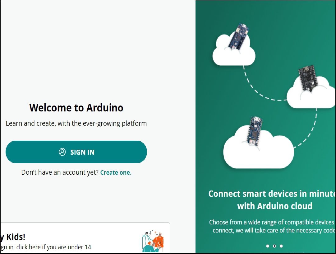
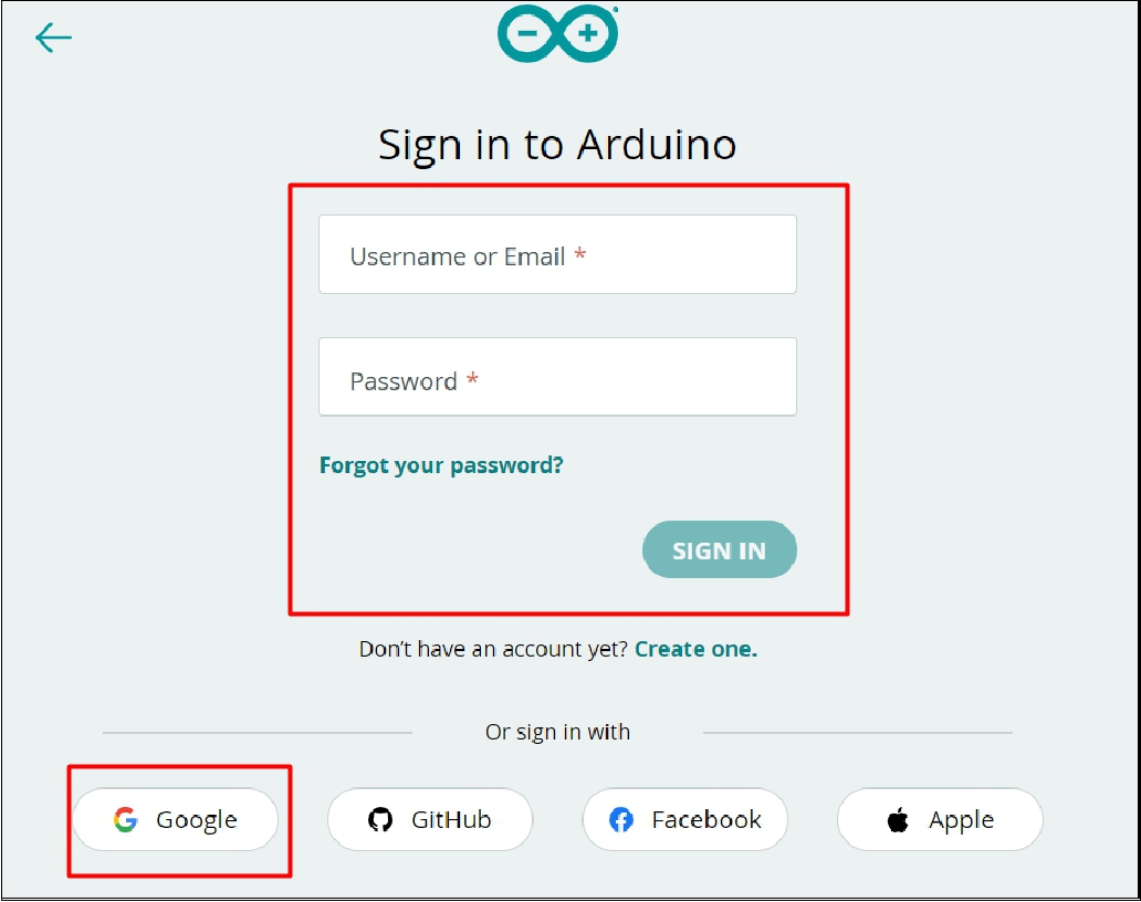
To use the XIAO ESP32-C3 with Arduino to connect to the Arduino IoT Cloud via Wi-Fi, follow these steps to configure and program your device:
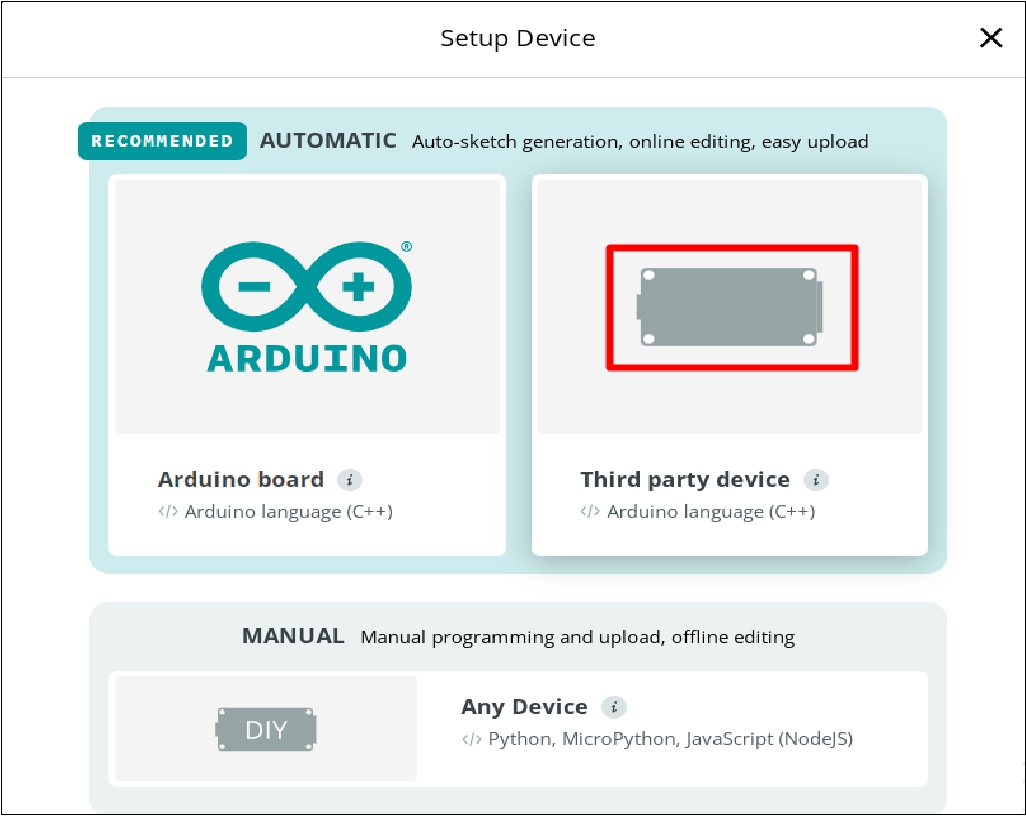
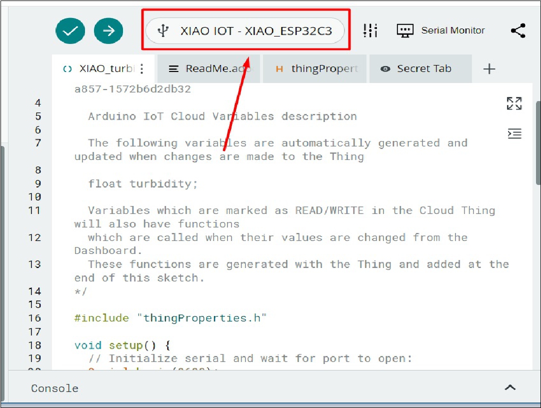
In setup we choose the correct board.
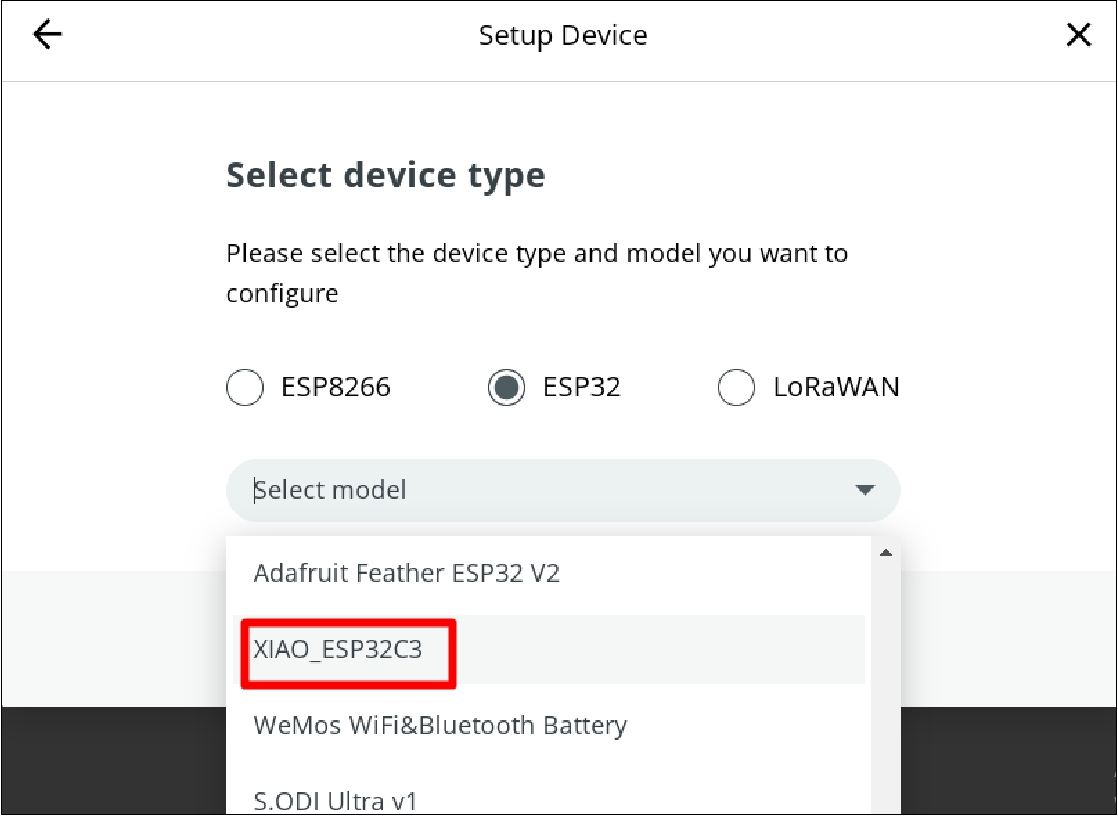
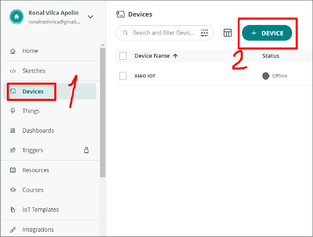
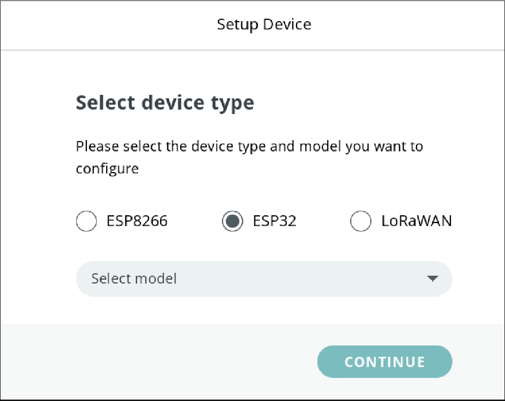
Now we select the correct device.
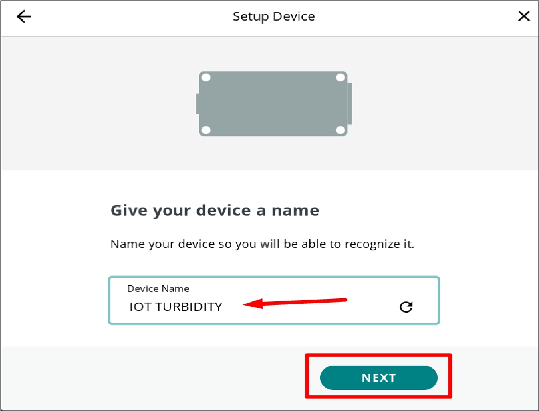
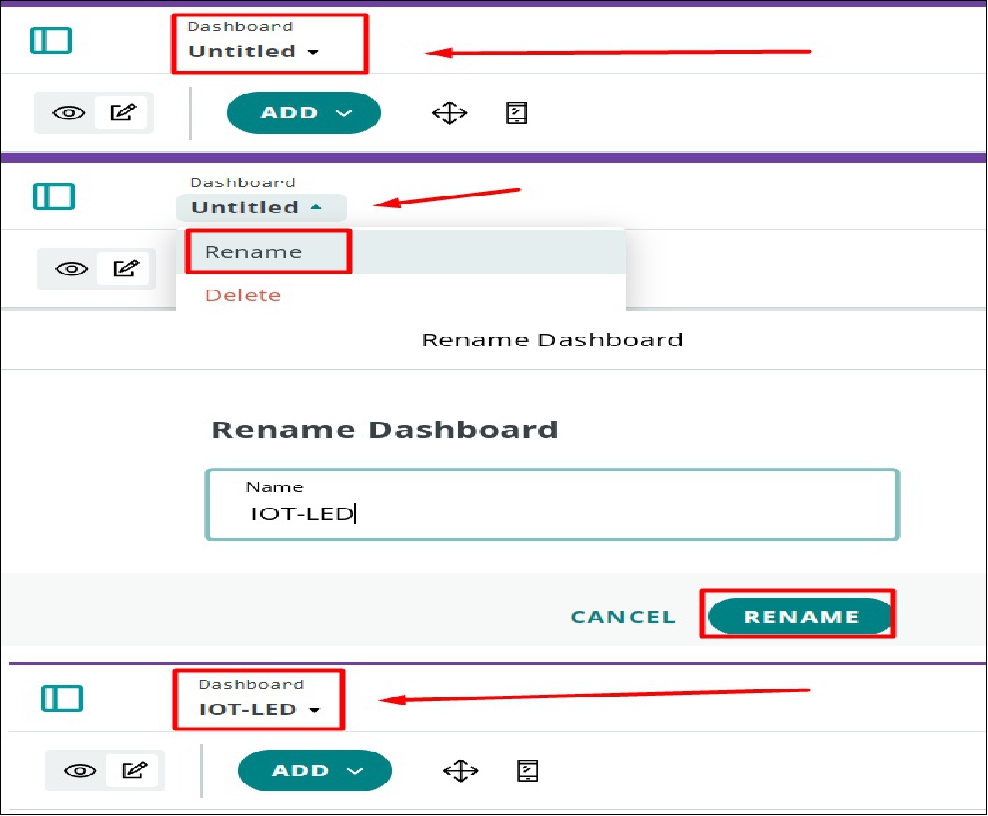
Naming the project.
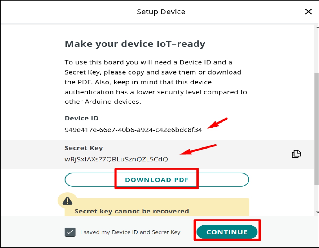
Downloading project credentials.
.
.
.
.
.
.
Implement the code necessary for your Arduino to communicate with the Arduino IoT Cloud. This includes configuring project parameters and reading/sending data to/from connected devices.
.
.
.
.
.
.
const int ledPin = 2; // Example: LED connected to pin 13
                                void loop() {
                                    ArduinoCloud.update();

                                    // Control del LED
                                    if (LEDControl) {
                                    digitalWrite(ledPin, HIGH); // on LED
                                    } else {
                                    digitalWrite(ledPin, LOW); // off LED
                                    }
                                }
.
.
.
.
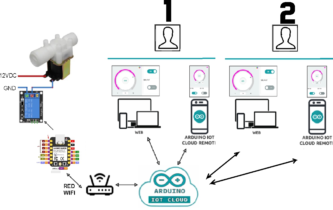
As part of my project, I implemented a system to measure water turbidity and conducted tests using three different types of water. This process allowed me to analyze and compare turbidity in different samples, thus contributing to the objectives and results of my research.
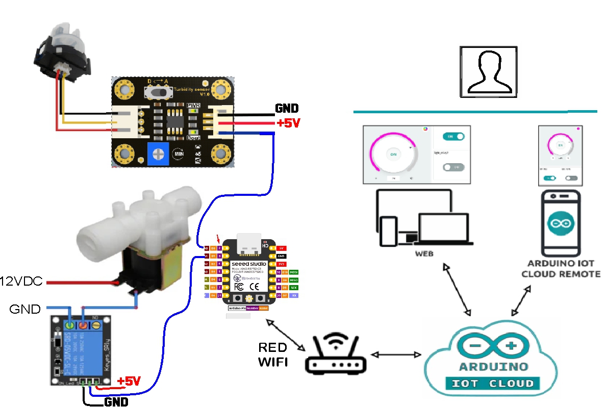
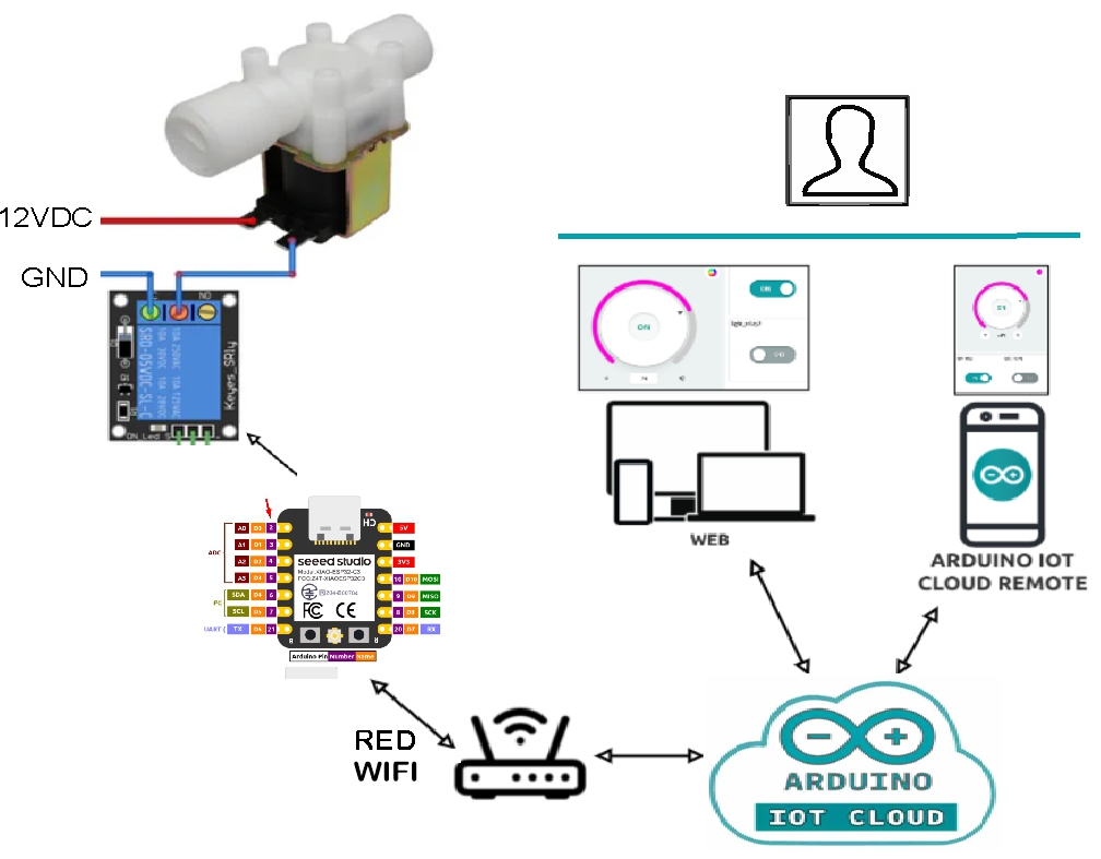
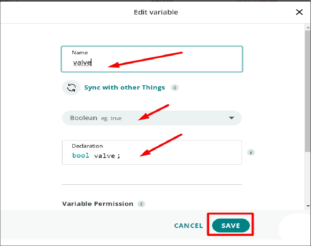
Once the account has been created, the next step in this process is to configure another device to be able to read the turbidity sensor data. In addition, it is required to implement the functionality to control the on and off of a solenoid valve. This stage will allow the integration of turbidity measurement capabilities with the control of the water treatment system, which is essential for the successful development of this project
.
.
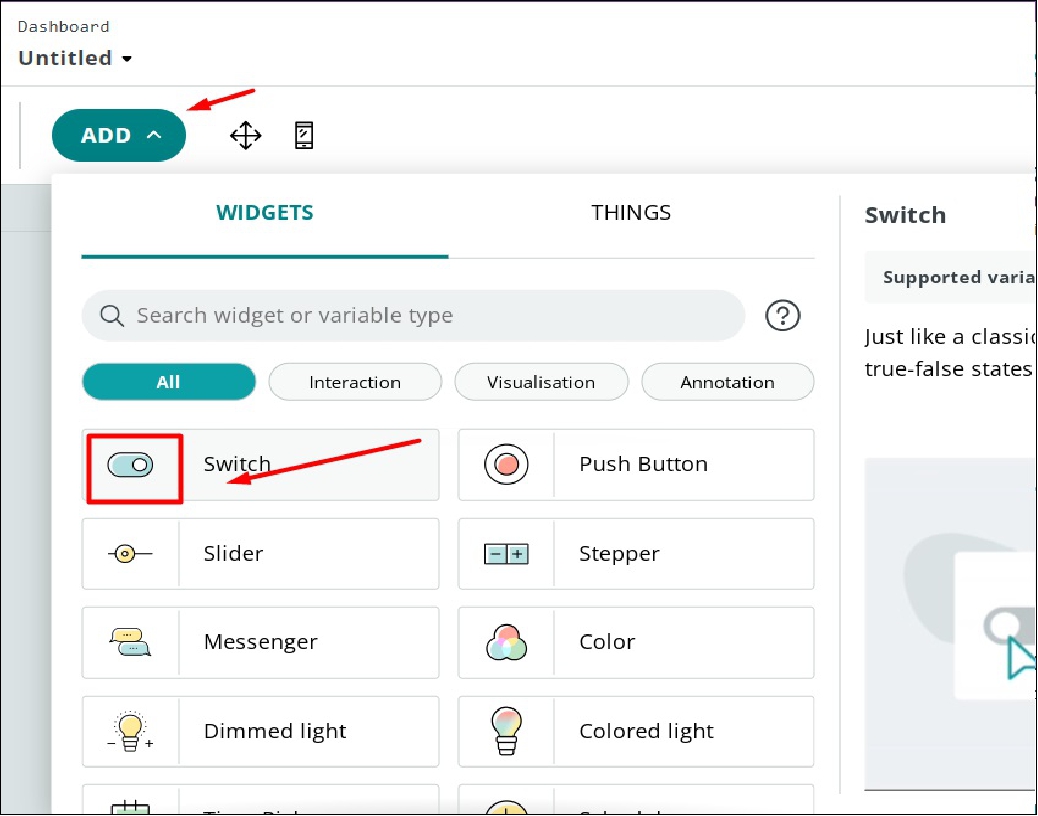
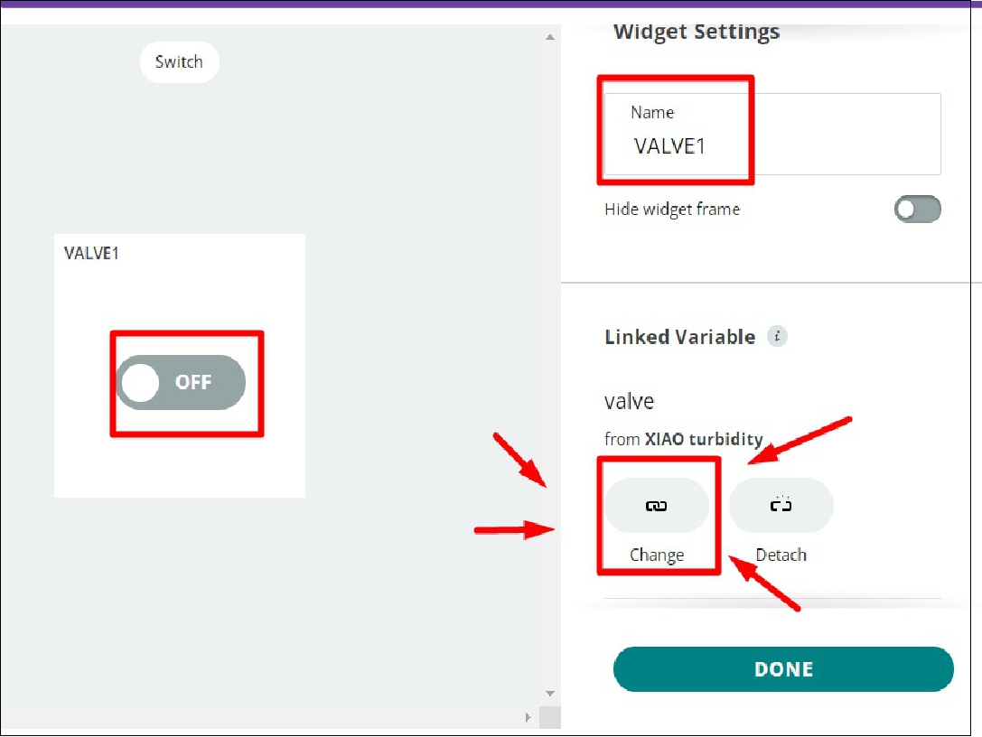
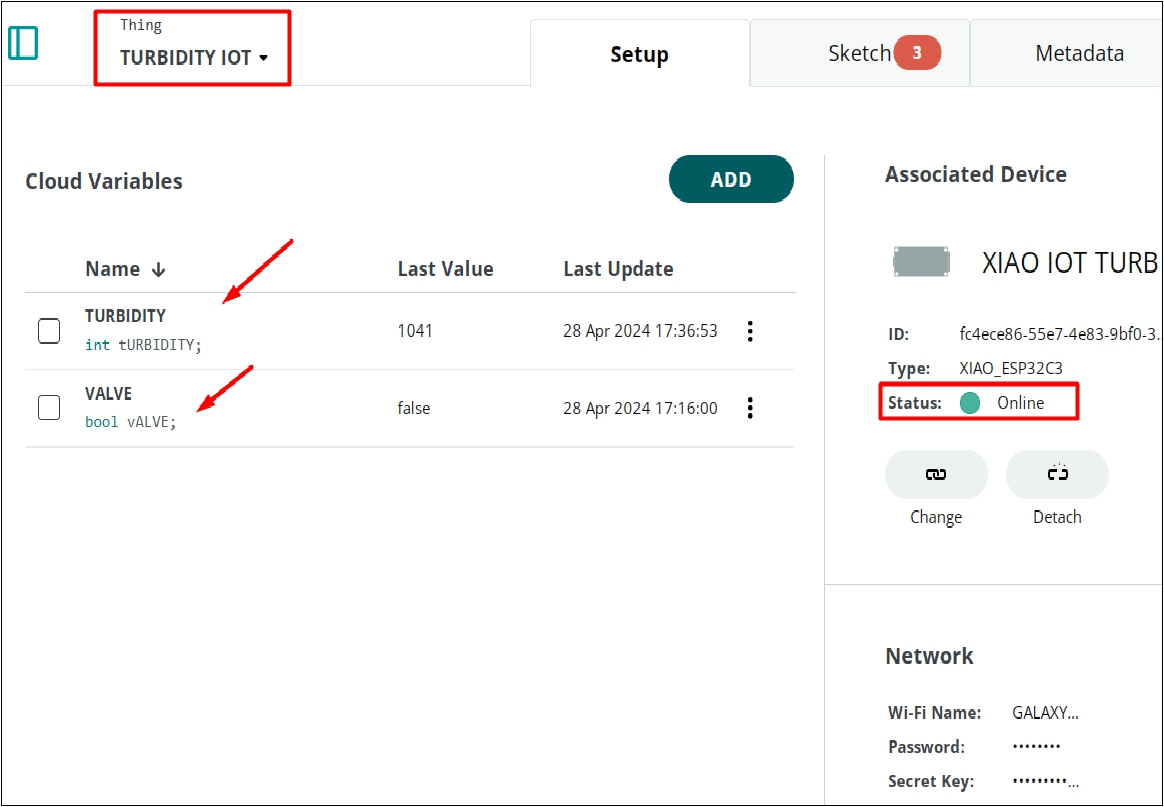
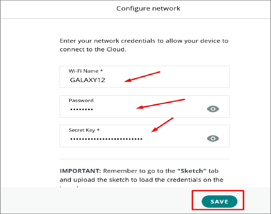
After that, we proceed to configure which sensors and outputs we want to display on the control panel (Dashboard). In addition, we select the appropriate device to integrate with the Dashboard and configure the WiFi network name, the network password and finally the security key (key) necessary for the connection. This configuration phase will allow us to customize and optimize the display of data in the Dashboard, ensuring a fluid and secure integration of our system with the network and the selected devices.
.
.
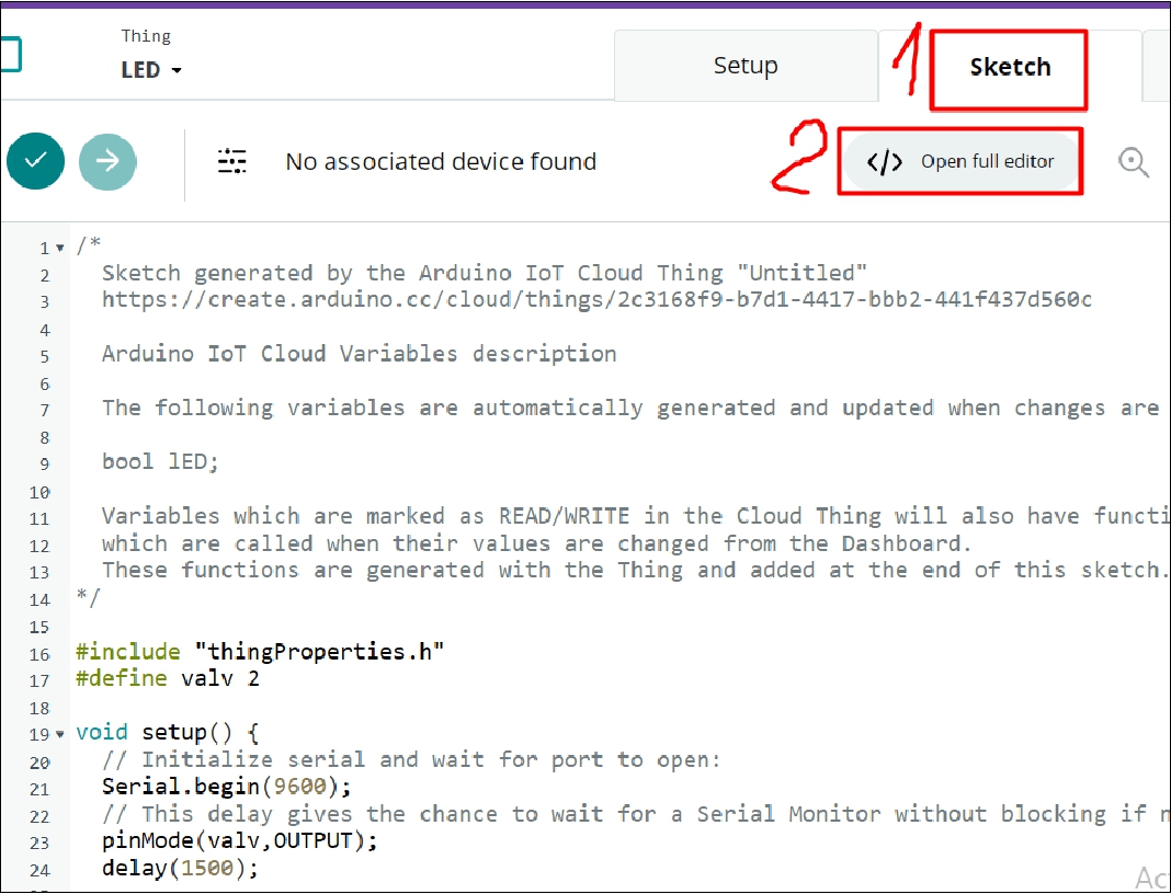
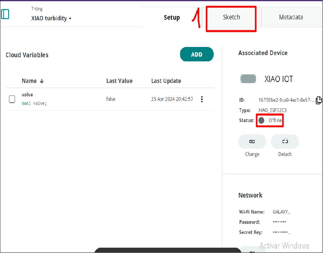
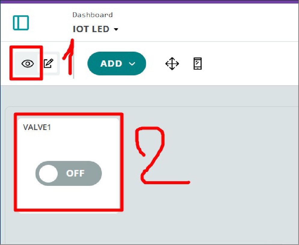
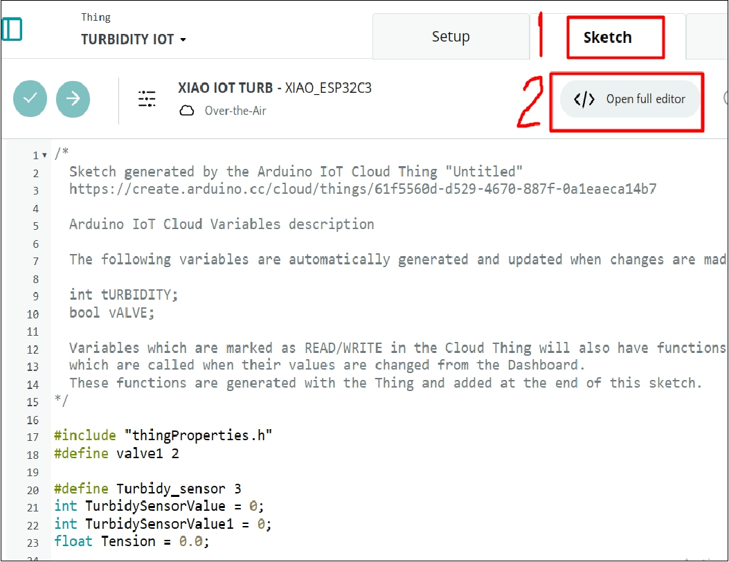
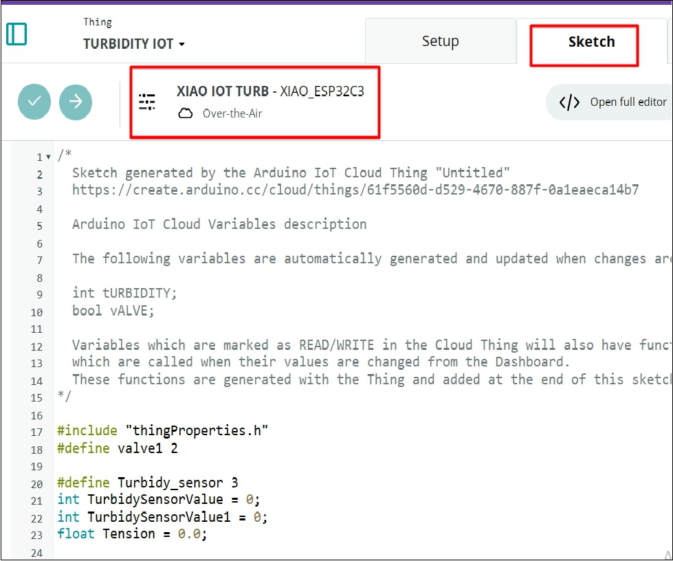
In the next step, we proceed to enter the integrated development environment (IDE) or Sketch, where we will write the code that will be loaded into the XIAO. To access this environment, we click on option number 2 called 'editor', which will take us to the workspace necessary to program and configure the XIAO ESP32 device.
.
.
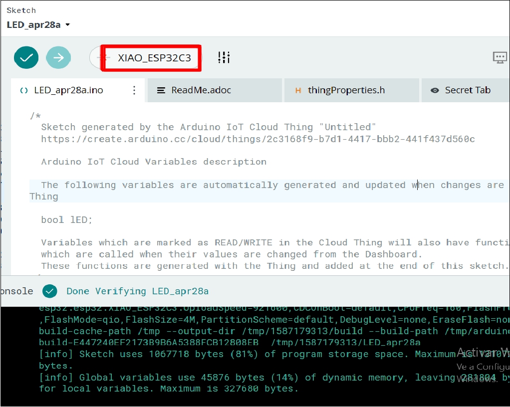
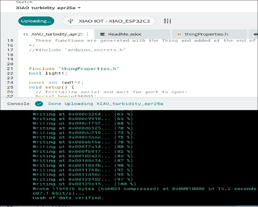
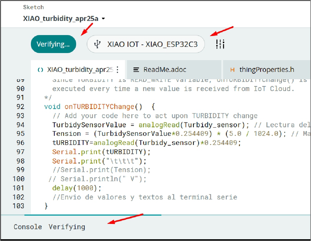
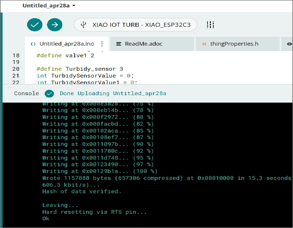
After this, we add our code and proceed to load it on our XIAO ESP32 device
.
.
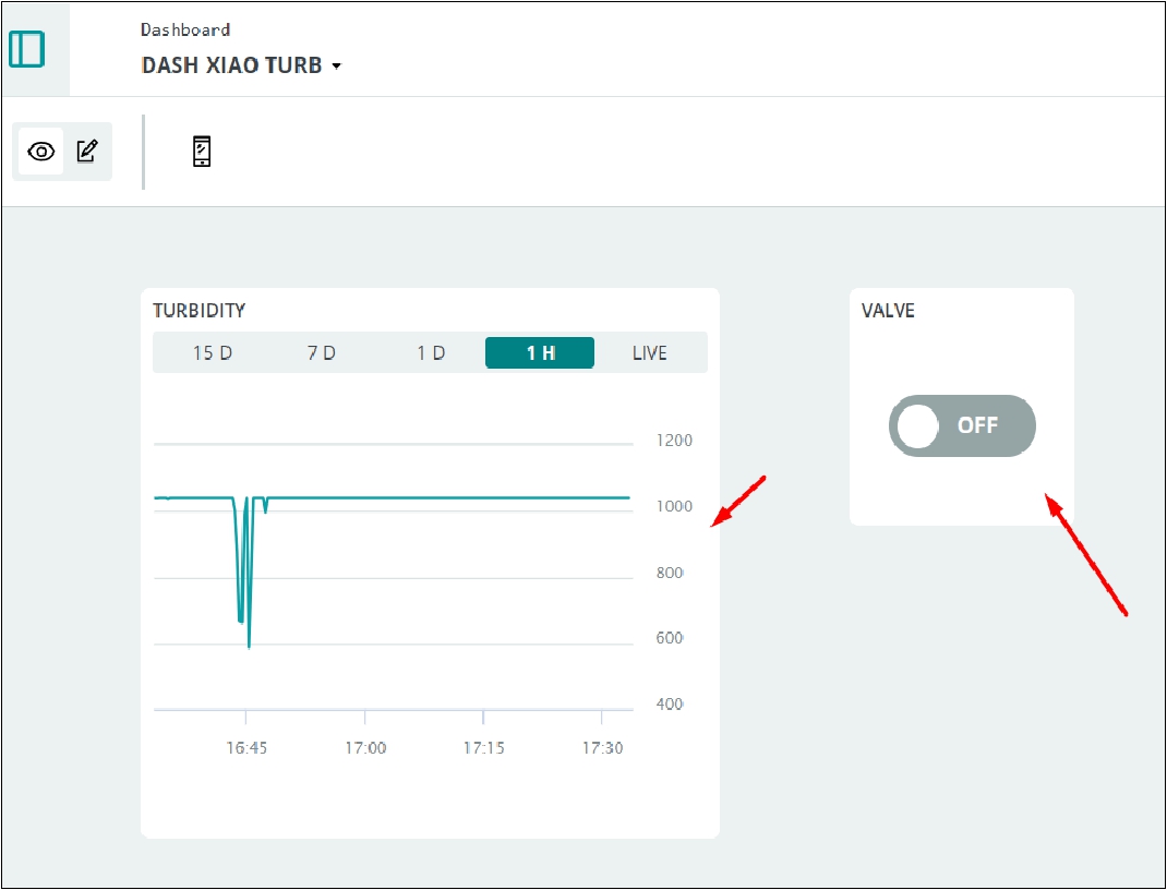
As a result of the values obtained, we can view the data from the turbidity sensor and control an actuator (such as a 220V pump) to activate or deactivate it.
.
I2C (Inter-Integrated Circuit) communication is a synchronous serial communication protocol used to connect electronic devices to each other on a printed circuit board or through short cables. It was developed by Philips Semiconductor (now NXP Semiconductors) in the 1980s and has become a de facto standard for communication between microcontrollers, sensors, actuators, memories and other peripheral devices.
Configure one of the Xiao ESP32-S3 as a master (sender) and the other as a slave (receiver) for I2C communication. You must assign unique addresses for each device in I2C communication.
Program your Arduino to send a numerical value through the serial port. For example, send the character '1' to turn the LED on the receiver on and '0' to turn it off.
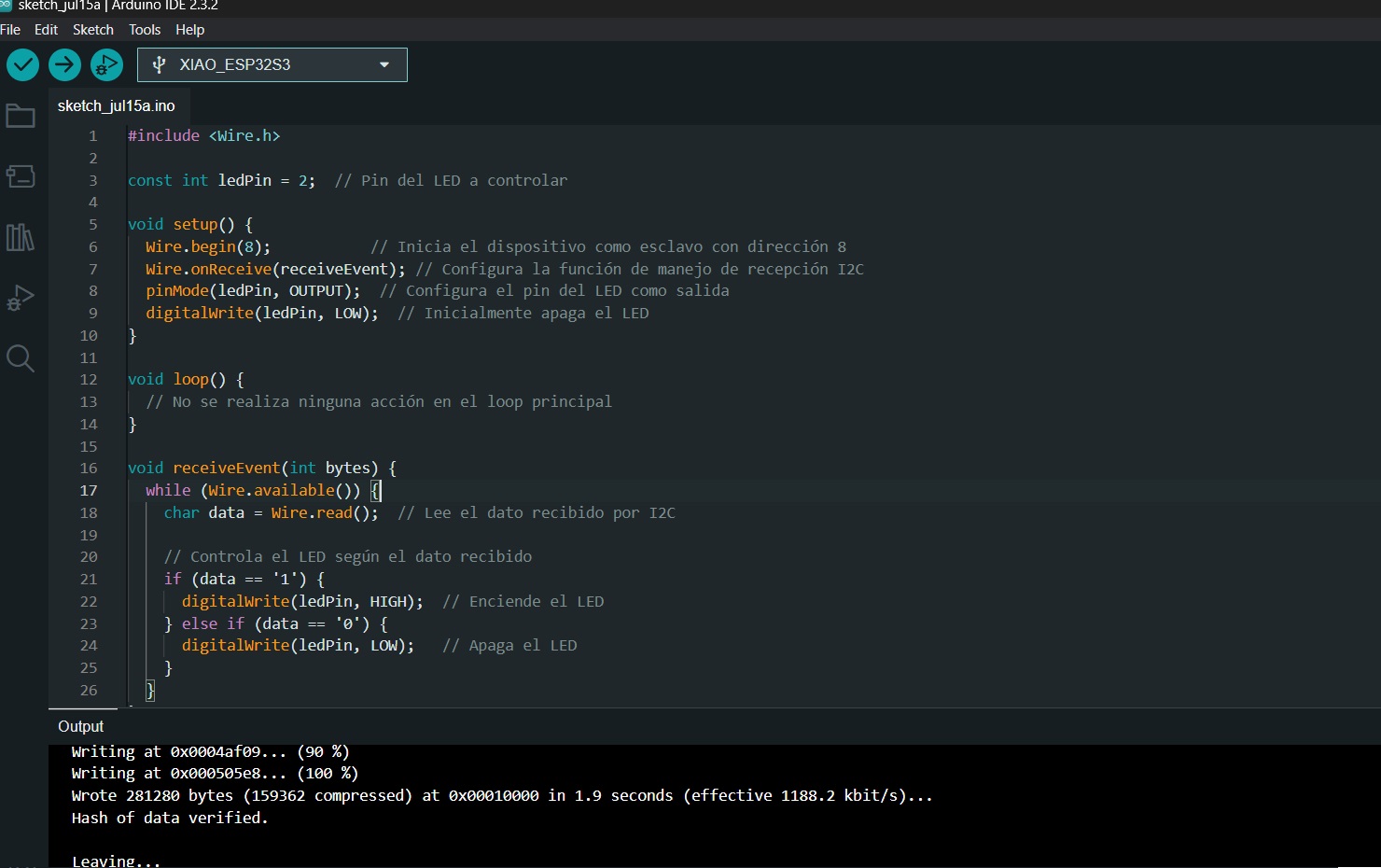
On the Xiao ESP32-S3 receiver, program it to read the data received by I2C from the Arduino through the serial port. Depending on the value received ('1' or '0'), it turns the corresponding LED on or off.
Use the appropriate functions and libraries on both Xiao ESP32-S3 to establish I2C communication. You can use the Wire library that is standard in Arduino and adapted for the ESP32.
Implement the logic in the Xiao ESP32-S3 receiver so that, upon receiving the correct value via I2C, it turns the connected LED on or off.
For communication I used, as I mentioned in the theory, a sender or master and a receiver or slave. For this, I used two XIAO ESP32-S3. On the receiver, I connected an LED to GPIO 2, which is activated by sending characters from the sender: a '1' to turn the LED on and a '0' to turn it off. All this is controlled from the emitter
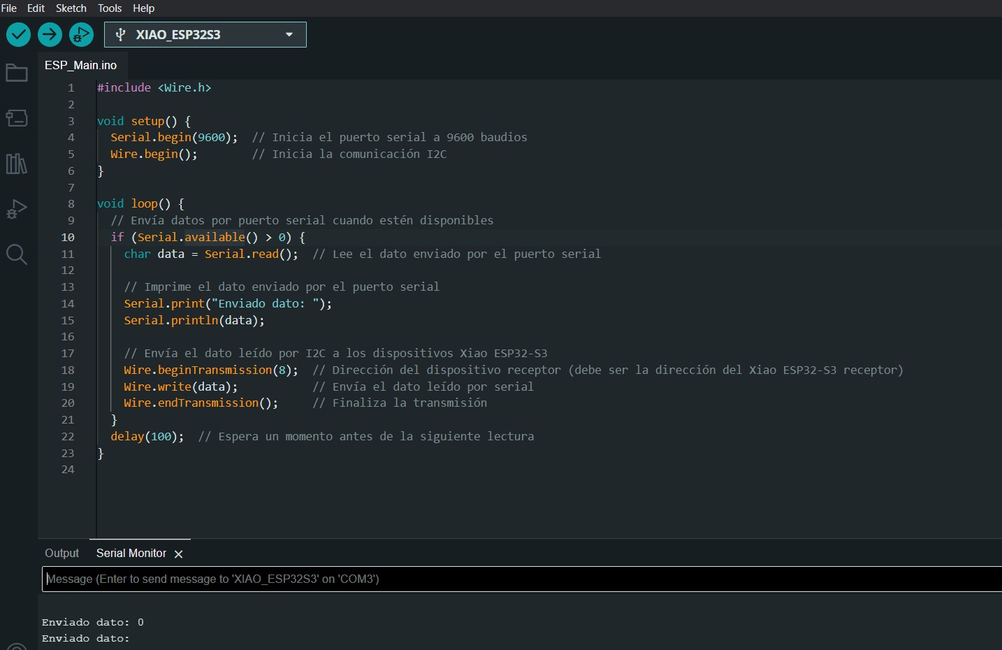
Issuer
Receiver
For my tests I used jumpers and a breadboard due to lack of time, as I needed to quickly test this type of communication. However, seeing what this communication protocol does, I will take the time necessary to design and manufacture their respective boards.
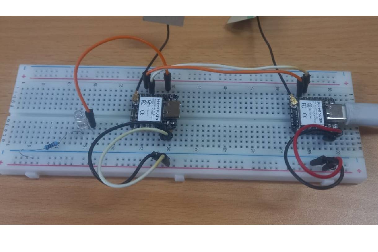
The following video shows the communication protocol implemented using two XIAO ESP32-S3. In the demonstration, the sender sends commands to control an LED connected to GPIO 2 of the receiver. I used jumpers and a breadboard for initial testing due to time constraints.
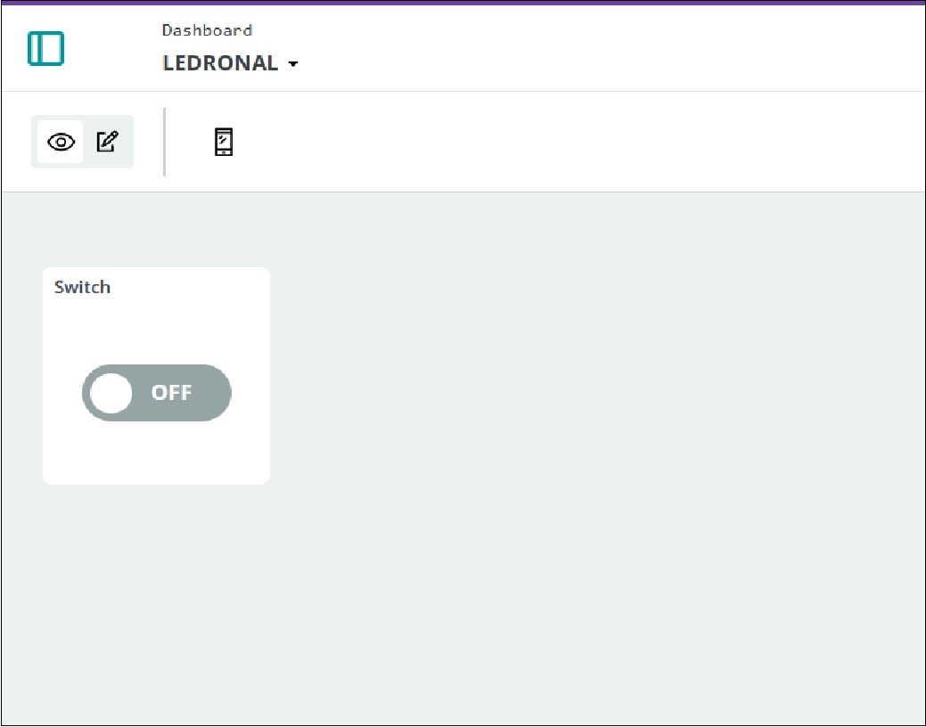
This week has been very productive, since I learned to establish communication between the XIAO ESP32 C3 and the WiFi, which has allowed me to control an actuator, in this case a solenoid valve, from a web platform. In addition, I was also able to turn this solenoid valve on and off from my cell phone, using the Arduino IOT cloud platform. I'm excited about the many applications and projects I can explore, such as integrating functionality with ALEXA and other applications.
However, not everything was so fast and fluid. I encountered some difficulties, such as the fact that some public institutions, such as the university where I work, impose certificates on their WiFi networks, which limits our total control over them. At first, I thought the problem was in my code, but after reviewing it thoroughly, I realized that everything was correct. To test it, I shared the connection from my cell phone as an access point and it worked without problems. This allowed me to confirm that everything was fine, and I was then able to test it on other WiFi networks in my house, where everything worked correctly.
1. Turbidity sensor test.ino
2. Receiver.ino
3. Transmitter.ino
Development of custom electronic boards with CNC Router.

Development of personalized keychains and ornaments with CNC Laser.
Development of custom machines "Desktop CNC Laser.

Huánuco is a Peruvian city, capital of the district, province and department of the same name in the north-central area of the country. The city has a population of 235,529 inhabitants. .